GD&T Symbols Reference & Feature Control Frame Builder
Learn the 14 GD&T symbols, tolerance zones and modifiers, and build a feature control frame to copy or download · free, no signup
See GD&T Symbols Reference & Feature Control Frame Builder in action
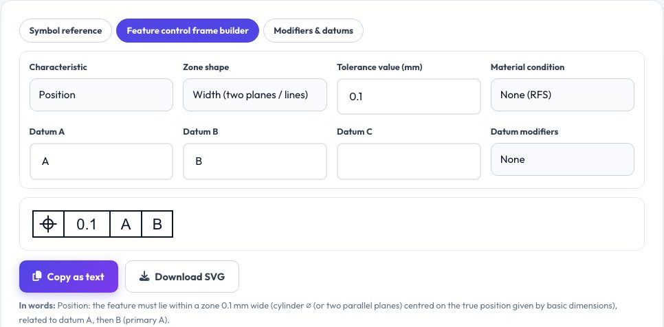
Free GD&T Symbols Reference & Feature Control Frame Builder
Geometric dimensioning and tolerancing (GD&T) is the symbolic language engineers use to control the form, orientation, location and runout of features on a drawing. This reference lists the 14 characteristic symbols — straightness, flatness, circularity, cylindricity, profile of a line, profile of a surface, perpendicularity, angularity, parallelism, position, concentricity, symmetry, circular runout and total runout — each drawn as a clean vector icon with its category, whether a datum is required, the shape of its tolerance zone, what it controls and a typical use, with search and category filters. The standards differ slightly: ASME Y14.5-2018 removed concentricity and symmetry, ISO 1101 keeps them, and the page says so.
The feature control frame builder lets you choose a characteristic, a cylindrical or spherical zone, a tolerance value, a material condition modifier (MMC or LMC) and up to three datums, shows the frame as you would draw it, explains it in plain English, flags mistakes such as a missing datum on a perpendicularity tolerance, and lets you copy it as text or download it as an SVG. A third tab explains modifiers and datum symbols: MMC, LMC, RFS, projected zone, free state, tangent plane, diameter, basic dimensions and datum targets.
Key features
14 symbols explained
Icon, category, datum rule, tolerance zone, meaning and typical use.
Frame builder
Characteristic, zone, value, modifier and datums with a live drawing.
Plain-English reading
Describes what the frame means and warns about common mistakes.
Modifiers and datums
MMC, LMC, RFS, projected zone, basic dimensions and more.
How to use it
- Browse or search the symbols.
- Open the builder and choose the characteristic and tolerance.
- Add datums and a modifier.
- Copy the frame text or download the SVG.
Worked example
Example
A position frame ⌖ | ⌀0.1 Ⓜ | A | B means the hole's axis must lie in a cylinder of 0.1 mm diameter (growing as the hole departs from its maximum-material size) located relative to datum A then datum B.
Who uses this tool
Engineering and design students
Learn GD&T symbols and rules.
Drafters and designers
Build frames correctly for drawings.
Machinists and inspectors
Interpret what a symbol demands.
Tips for the best results
- Remember form tolerances (flatness, straightness) have no datums.
- A position tolerance needs basic dimensions and datums.
- Order datums primary, secondary, tertiary.
- Always follow the standard cited on your drawing.
Common mistakes to avoid
- Using perpendicularity without a datum.
- Confusing runout with concentricity.
- Treating a tolerance zone's width as a ± value.
Why use AZRS QuickFix?
It is 100% free, needs no signup and has no watermark or usage limits. The tool runs in your browser, so what you type stays on your device, and it works on phones, tablets and desktops. New tools are added every week — bookmark this page or browse the full QuickFix toolbox.
Frequently asked questions
ASME or ISO?
They are similar but not identical; this page notes the main differences.
What is MMC?
Maximum material condition — the size with the most material, which grants bonus tolerance.
Does it check my drawing?
No, it is a learning and drafting aid.
Is it free?
Yes.