Heat-Set Insert, Screw Hole & 3D-Print Tolerance Chart
Hole sizes for heat-set inserts, screws and press fits by printer type · free, no signup
See Heat-Set Insert, Screw Hole & 3D-Print Tolerance Chart in action
Heat-Set Insert, Screw Hole & Fit Tolerance Chart for 3D Printing
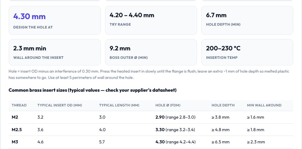
Getting holes right is the difference between a part that assembles and a part that goes in the bin. This page has three tools. The heat-set insert calculator takes the insert's outside diameter, your process (FDM, big nozzle, resin), material and hole direction and returns the diameter to design, a trial range, the minimum hole depth, the wall needed around the insert and the insertion temperature. A table lists typical sizes for M2–M8 inserts.
The screw tab lists ISO clearance holes (close, normal, loose), self-tapping pilot holes for plastic and tap drill sizes, with the printing compensation you should add. The fit tab gives press-fit, snug, sliding, loose, print-in-place and snap-fit clearances for FDM, resin and SLS/MJF — and a calculator that turns your nominal shaft diameter into the hole diameter to model, including the extra allowance for small or horizontal FDM holes.
Key features
Heat-set insert calculator
Hole diameter, depth, wall thickness and temperature for your insert and material.
Screw & pilot hole chart
ISO 273 clearances, self-tapping pilot holes and tap drills for M2–M8.
Fit calculator
Press, slide, loose and print-in-place clearances for FDM, resin and SLS.
Printer-specific allowances
Adds the extra tolerance for small and horizontal FDM holes.
How to use it
- Choose the tab for inserts, screws or fits.
- Enter your insert OD, screw size or nominal diameter.
- Select your printing process and orientation.
- Model the hole at the result and test-print a coupon.
Worked example
Example
A 4.6 mm OD brass insert for M3 in PLA on FDM: design the hole at 4.3 mm (range 4.2–4.4 mm), at least 6.7 mm deep with 2.3 mm of wall around it, inserting at 200–230 °C.
Who uses this tool
CAD students and engineers
Quick, defensible hole sizes.
Makers building enclosures
Heat-set inserts that hold.
Anyone designing print-in-place parts
Right clearances per process.
Tips for the best results
- Always print a one-minute coupon with five holes in 0.1 mm steps to calibrate your machine.
- Leave 1 mm of extra hole depth below the insert for displaced plastic.
- Small FDM holes print undersize; add 0.1 mm below 4 mm diameter.
- Horizontal holes sag at the top — consider teardrop shapes.
Common mistakes to avoid
- Modelling holes at nominal size and finding bolts will not fit.
- Using the same clearance for FDM and resin.
- Too little wall around an insert, causing cracking.
Why use AZRS QuickFix?
It is 100% free, needs no signup and has no watermark or usage limits. The tool runs in your browser, so what you type stays on your device, and it works on phones, tablets and desktops. New tools are added every week — bookmark this page or browse the full QuickFix toolbox.
Frequently asked questions
Are the insert OD values exact?
Insert dimensions vary by supplier; use your datasheet value — the calculator formula is based on OD.
Why different clearances for resin?
Resin prints more accurately, so smaller gaps work; SLS needs larger gaps for powder removal.
What is a pilot hole?
The pre-drilled hole for a self-tapping screw in plastic, about 0.8× the screw's major diameter.
Is this a replacement for testing?
No — use it as a starting point and verify with a print.