Heat Sink & Thermal Resistance Calculator
Required heat-sink thermal resistance, finned heat-sink estimate, interface conduction and regulator heat · free, no signup
See Heat Sink & Thermal Resistance Calculator in action
Free Heat Sink & Thermal Resistance Calculator
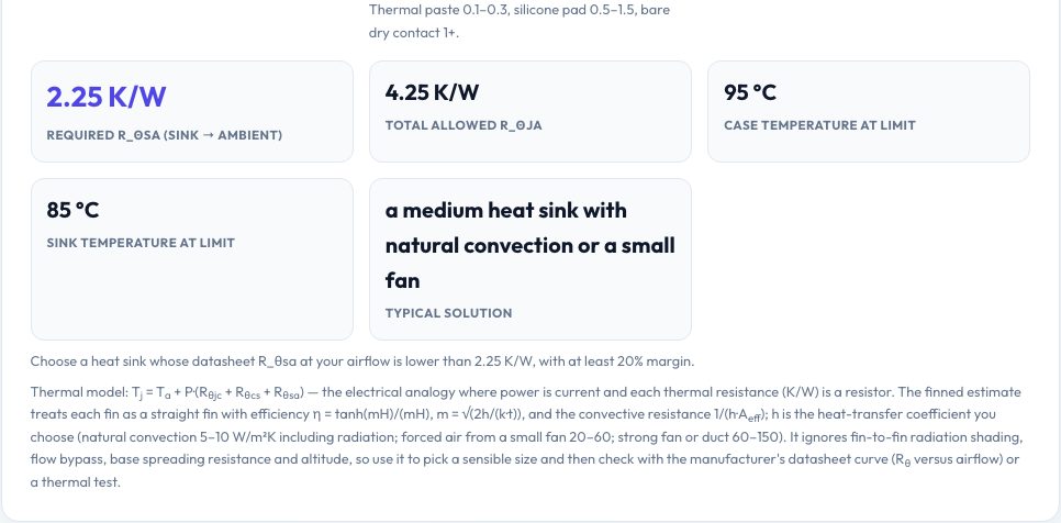
A heat sink is described by one number — its thermal resistance to ambient in K/W — and sizing one starts from the thermal 'Ohm's law': T_junction = T_ambient + P × (Rθjc + Rθcs + Rθsa). Enter the power to dissipate, the ambient temperature, the maximum junction temperature and the datasheet junction-to-case resistance and the interface (paste or pad) resistance, and the calculator returns the heat-sink resistance you need, the allowed total resistance and the case and sink temperatures at the limit, with a plain-language hint about what kind of heat sink that implies.
A second tab estimates an extruded finned heat sink from its width, length, fin count, thickness, height and base thickness, the material (6063 or 6061 aluminium, copper, die-cast) and an airflow setting, using straight-fin efficiency η = tanh(mH)/(mH) to find the effective area and the resulting thermal resistance, with warnings about fin spacing and efficiency. A third tab gives conduction through a thermal pad or paste (R = t/kA) and the heat generated by a linear regulator, (Vin − Vout) × I.
Key features
Required Rθsa
From power, ambient, junction limit, Rθjc and Rθcs.
Finned sink estimate
Fin efficiency, effective area, resistance, fin gap and mass.
Interface and regulator tools
Thermal pad conduction and linear-regulator dissipation.
Practical warnings
Fin spacing for natural convection, efficiency and margin advice.
How to use it
- Enter power, ambient and junction limit with the thermal resistances.
- Read the heat-sink resistance you need.
- Use the finned sink tab to try dimensions and airflow.
- Check the interface and regulator heat on the last tab.
Worked example
Example
For 20 W with 40 °C ambient, a 125 °C junction limit, Rθjc = 1.5 K/W and a 0.5 K/W pad you need a heat sink of 2.25 K/W or better; a 100 × 100 mm sink with twelve 25 mm × 1.5 mm fins in natural convection comes out around 1.45 K/W.
Who uses this tool
Electronics designers
Pick heat sinks for regulators, MOSFETs and LEDs.
3D printer and PC builders
Check cooling for drivers and CPUs.
Students
Learn the thermal resistance network.
Tips for the best results
- Leave 20% margin on the calculated resistance.
- Use thermal paste instead of dry contact.
- Natural convection needs at least 4–6 mm fin spacing.
- Anodised or black-finished sinks radiate a little better.
Common mistakes to avoid
- Forgetting the interface resistance between the case and the sink.
- Using a heat sink's forced-air rating without airflow.
- Designing to the absolute maximum junction temperature.
Why use AZRS QuickFix?
It is 100% free, needs no signup and has no watermark or usage limits. The tool runs in your browser, so what you type stays on your device, and it works on phones, tablets and desktops. New tools are added every week — bookmark this page or browse the full QuickFix toolbox.
Frequently asked questions
What is Rθjc?
Junction-to-case thermal resistance from the component datasheet.
What h should I use?
About 5–10 W/m²K in still air, 20–60 with a small fan.
Is the fin estimate exact?
It is a first-order estimate; verify with the manufacturer's curve.
Is it free?
Yes.